

Description
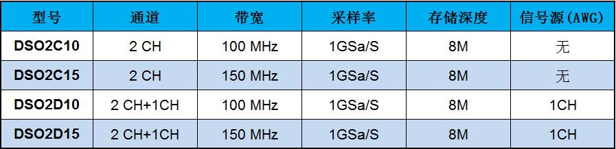
| model | DSO2D15 | DSO2D10 | DSO2C15 | DSO2C10 |
| bandwidth | 150MHz | 100MHz | 150MHz | 100MHz |
| Number of oscilloscope channels | 2CH | 2CH | 2CH | 2CH |
| Built-in signal source | 1CH | 1CH | – | – |
| Oscilloscope Specifications | ||||
| Sample rate range | 1GSa/s (single channel), 500MSa/s (dual channel) | |||
| Collection method | ||||
| sampling | Sample data | |||
| peak-to-peak | Displays high frequency and random glitches | |||
| average value | Average waveform, times: 4, 8, 16, 32, 64, 128 | |||
| enter | ||||
| input coupling | DC, AC or ground (DC, AC, GND) | |||
| input resistance | 1MΩ±2% ‖20pF±3pF | |||
| Probe attenuation factor setting | 1X, 10X, 100X, 1000X | |||
| Voltage level | 300V CAT II | |||
| Maximum input voltage | 300VRMS (10X) | |||
| horizontal system | ||||
| waveform interpolation | (sin x)/x | |||
| maximum record length | Single channel maximum 8M | |||
| Dual channel maximum 4M | ||||
| Horizontal scale range | 2ns/div~100s/div 1, 2, 5 steps | |||
| time base mode | YT, XY, Roll | |||
| Incremental time measurement accuracy | One-shot, “Sampling” mode | |||
| (full bandwidth) | ±(1 sampling interval+100ppm×reading+0.6ns) | |||
| >16 times average | ||||
| ±(1 sampling interval+100ppm×reading+0.4ns) | ||||
| Sampling interval = seconds/div ÷ 200 | ||||
| Sample Rate and Delay Time Accuracy | ±50ppm (at any time interval greater than 1ms) | |||
| vertical system | ||||
| model | DSO2D15 | DSO2D10 | DSO2C15 | DSO2C10 |
| bandwidth | 150MHz | 100MHz | 150MHz | 100MHz |
| Rise time at BNC (typical) | 2.4ns | 3.5ns | 2.4ns | 3.5ns |
| vertical resolution | 8-bit resolution, each channel is sampled simultaneously | |||
| vertical sensitivity | 2mV/div to 10V/div | |||
| offset range | ≤200mV/div, ±1V; | |||
| >200mV/div, ±50V | ||||
| computation | Add, Subtract, Multiply, Divide, FFT | |||
| FFT | Windows: Rectangular, Henning, Hemming, Blackman, Bartlett, Flat Top | |||
| Bandwidth limit | 20MHz | |||
| Low frequency response (-3db) | ≤10Hz at BNC | |||
| Vertical Gain Accuracy | ±3% accuracy from 10V/div to 10mV/div in “Sampling” or “Averaging” acquisition mode; | |||
| ±4% accuracy from 5mV/div to 2mV/div in “sample” or “average” acquisition mode | ||||
| Voltage measurement repeatability, average acquisition mode | Voltage delta between any two averages of ≥16 waveforms acquired under the same setup and ambient conditions: ±(3% x reading + 0.05 divisions) | |||
| Note: Bandwidth reduced to 6MHz when using X1 probe | ||||
| trigger system | ||||
| trigger type | Edge, Pulse, Video, Slope, Timeout, Window, Pattern, Interval, Runt, UART, LIN, CAN, SPI, IIC | |||
| Trigger level range | ±5 grids from the center of the screen | |||
| trigger mode | Auto, Normal, Single | |||
| level | CH1~CH2 | ±4 divisions from the center of the display | ||
| EXT | 0~3.3V | |||
| Holdoff range | 16ns~10s | |||
| Trigger level accuracy | CH1~CH2 | 0.2 divisions × volts/div within ±4 divisions from the center display | ||
| EXT | ±(6% of set value + 40mV) | |||
| edge-triggered | slope | rising edge, falling edge, rising edge or falling edge | ||
| source | CH1, CH2, EXT | |||
| Pulse width trigger | polarity | positive polarity, negative polarity | ||
| Condition (When) | <, >, !=, = | |||
| source | CH1~CH2, | |||
| Pulse width range | 8ns ~ 10s | |||
| precision | 8ns | |||
| video trigger | Signal standard | NTSC, PAL | ||
| source | CH1~CH2 | |||
| Synchronize | Scan Lines, Lines, Odd Fields, Even Fields, All Fields | |||
| Slope trigger | slope | Rise and fall | ||
| Condition (When) | <, >, !=, = | |||
| source | CH1 ~ CH2 | |||
| time limit | 8ns ~ 10s | |||
| precision | 8ns | |||
| Timeout trigger | source | CH1~CH2, | ||
| polarity | positive polarity, negative polarity | |||
| time limit | 8ns ~ 10s | |||
| precision | 8ns | |||
| window trigger | source | CH1~CH2 | ||
| Pattern trigger | pattern | 0: low level; 1: high level; X: ignore; : rising; : falling; : rising or falling | ||
| Level (source) | CH1~CH2 | |||
| interval trigger | slope | Rise and fall | ||
| Condition (When) | <, >, !=, = | |||
| source | CH1~CH2, | |||
| time limit | 8ns ~ 10s | |||
| precision | 8ns | |||
| runt trigger | polarity | positive polarity, negative polarity | ||
| Condition (When) | <, >, !=, = | |||
| source | CH1~CH2 | |||
| time limit | 8ns ~ 10s | |||
| precision | 8ns | |||
| UART trigger | Condition (When) | start, stop, data, parity, receive error | ||
| Source (RX/TX) | CH1~CH2 | |||
| Data Format | Hex (hex) | |||
| Data length | 1 byte | |||
| data bit width | 5 bits, 6 bits, 7 bits, 8 bits | |||
| parity | None, Odd, Even | |||
| idle level | high, low | |||
| baud rate (optional) | 110/300/600/1200/2400/4800/9600/14400/19200/38400/57600/115200/230400/380400/460400 bit/s | |||
| Baud rate (custom) | 300bit/s~334000bit/s | |||
| LIN trigger | Condition (When) | Space Field, Sync Field, ID Field, Sync Error, Identifier, ID and Data | ||
| source | CH1~CH2, | |||
| Data Format | Hex (hex) | |||
| baud rate (optional) | 110/300/600/1200/2400/4800/9600/14400/19200/38400/57600/115200/230400/380400/460400 bit/s | |||
| Baud rate (custom) | 300bit/s~334000bit/s | |||
| CAN trigger | Condition (When) | Start Bit, Remote Frame ID, Data Frame ID, Frame ID, Remote Frame Data, Data Frame Data, Error Frame, All Errors, Acknowledge Error, Overload Frame | ||
| source | CH1~CH2 | |||
| Data Format | Hex (hex) | |||
| baud rate (optional) | 10000, 20000, 33300, 500000, 62500, 83300, 100000, 125000, 250000, 500000, 800000, 1000000 | |||
| Baud rate (custom) | 5kbit/s~1Mbit/s | |||
| SPI trigger | source | CH1~CH2, | ||
| Data Format | Hex (hex) | |||
| data bit width | 4, 8, 16, 24, 32 | |||
| IIC trigger | Source (SDA/SCL) | CH1~CH2, | ||
| Data Format | Hex (hex) | |||
| data index | 0~7 | |||
| timing (condition) | Start Bit, Stop Bit, No Acknowledge, Address, Data, Restart | |||
| Measurement | ||||
| cursor | Voltage difference between cursors △V | |||
| Time difference between cursors △T | ||||
| Reciprocal of ΔT, in Hertz (1/ΔT) | ||||
| automatic measurement | Frequency, Period, Average, Peak-Peak, RMS, Min, Max, Rise Time, Fall Time, Positive Pulse Width, Negative Pulse Width, Bottom Value, Top Value, Mid Value, Amplitude, Overshoot , Preshoot, Rising Edge Phase Difference, Falling Edge Phase Difference, Positive Duty Cycle, Negative Duty Cycle, Cycle Average, Cycle RMS, Falling Edge Overshoot, Rising Edge Preshoot, BWIDTH, FRF, FFR, LRR , LRF, LFR, LFF | |||
| DVM | data source | CH1, CH2 | ||
| Measurement type | DC RMS | |||
| AC RMS | ||||
| DC | ||||
| frequency meter | Hardware 6-bit frequency counter | |||
| Signal source indicator | ||||
| Number of channels | 1 channel | |||
| Sampling Rate | 200MSa/s | |||
| vertical resolution | 12 bits | |||
| highest frequency | 25MHz | |||
| Standard waveform | Sine, Square, Pulse, Triangle, Sample, Exponential, Noise | |||
| Arbitrary waveform | Arb1, Arb2, Arb3, Arb4 | |||
| Sine | Frequency Range | 0.1Hz~25MHz | ||
| Square wave/pulse | Frequency Range | 0.1Hz~10MHz | ||
| triangle wave | Frequency Range | 0.1Hz~1MHz | ||
| sample wave | Frequency Range | 0.1Hz~1MHz | ||
| Exponential Wave | Frequency Range | 0.1Hz~5MHz | ||
| noise | ||||
| Arbitrary Wave 1 | Frequency Range | 0.1 Hz to 10 MHz | ||
| Arbitrary Wave 2 | Frequency Range | 0.1 Hz to 10 MHz | ||
| Arbitrary Wave 3 | Frequency Range | 0.1 Hz to 10 MHz | ||
| Arbitrary Wave 4 | Frequency Range | 0.1 Hz to 10 MHz | ||
| Waveform length | 4KSa | |||
| frequency | precision | 100 ppm (less than 10 kHz) 50 ppm (more than 10 kHz) | ||
| Resolution | 0.1 Hz or 4 bits, whichever is greater | |||
| Amplitude | output range | 10mV~7Vp-p (high impedance) | ||
| 5mV~3.5Vp-p(50Ω) | ||||
| DC offset | scope | ±3.5 V, high impedance | ||
| ±1.75V, 50Ω | ||||
| Resolution | 100 μV or 3 bits, whichever is greater | |||
| output impedance | 50Ω | |||
| General technical specifications | ||||
| show | Display type | 7″ TFT LCD display diagonally | ||
| Display resolution | 800 (horizontal)*480 (vertical) pixels | |||
| Afterglow time | Min, 1 s, 5 s, 10 s, 30S, infinite | |||
| display type | point, vector | |||
| Display brightness | adjustable | |||
| grid type | optional | |||
| grid brightness | adjustable | |||
| interface | Standard interface | USB Host, USB Device | ||
| General technical specifications | Probe Compensator Output | |||
| Output voltage, typical | About 2Vpp input ≥1MΩ load | |||
| frequency, typical | 1kHz | |||
| voltage | 100-120VAC RMS (±10%), 45Hz to 440Hz, CATⅡ | |||
| 120-240VAC RMS (±10%), 45Hz to 66Hz, CATⅡ | ||||
| Power consumption | less than 30W | |||
| fuse | T, 3.15A, 250V, 5x20mm | |||
| operating temperature | 0~50 °C (32~122 °F) | |||
| storage temperature | -40~+71 °C (-40~159.8 °F) | |||
| humidity | ≤+104℉(≤+40°C): ≤90% relative humidity | |||
| 106°F~122°F (+41°C ~50°C): ≤60% relative humidity | ||||
| Altitude | When operating and when not operating | 3,000m (10,000ft) | ||
| mechanical shock | random vibration | 0.31 g RMS from 50Hz to 500Hz , | ||
| 10 minutes per axis | ||||
| when not in operation | 2.46g RMS from 5Hz to 500Hz , | |||
| 10 minutes per axis | ||||
| while operating | 50g, 11ms, half sine wave | |||
| Mechanical part | Oscilloscope size | 318 x 110 x 150mm(L x W x H) | ||
| weight | 1900g | |||


Reviews
There are no reviews yet.